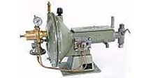
Detail TEXSTEAM PUMP ~ SERIES 3700
TEXSTEAM PUMP SERIES 3700
GAS OR AIR POWERED CHEMICAL INJECTORS
DESCRIPTION
Texsteam series 3700 chemical injectors are pneumatically powered and designed for handling many types of aqueous solutions and other chemicals. Single or double-headed units with three volume adjustments are available in a wide variety of models. Injection pressure to 1500 psi can be achieved with
air or gas pressure as low as 50 psi. Units can be furnished with or without reservoirs ( 5 or 10 gallon.
other sizes available upon request) . Texsteam 3700 injectors feature a unitized gas motor and pump.
The gas motor operates in an enclosed oil bath. All motor and pump parts are fully protected against
dirt and the elements. The 3700 series’ efficient ratchet-type mechanism is noted for its long-life and
accurate control.
APPLICATIONS
• Blending and proportioning chemical compounds in general process plant operation
• Introducing solvents, de-emulsifiers, desalters and flocculants
• High pressure bearing lubrication
• Injection of methanol into gas pipe-lines
• Lubrication of mechanical seals in pumps and machinery relying upon this type seal
• Water treatment
• Corrosion Inhibitor injection
• Sampling
• Introduction of measured quantities of highly toxic bactericides
• Both low and high-viscosity fluids and non-abrasive slurries can be handled with this pump
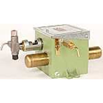
GENERAL ASSEMBLY
Outstanding Features - Chemical Injectors
Single and Double Headed Units Available ( one tank furnished with each head)
Type 3700 S is designed for operation of low uniform pressures of 50 psi and less. Unitized with five gallon container and single injector head. Furnished with slight feed only… no fittings.
Shipping Weight: 55 pounds ( packed in cardboard carton) .
Type 3700 SL is designed for operation of low uniform pressure of 50 psi or less. Unitized with five gallon container and single injector head. Furnished with level gage and the following fittings: five feet
of 5/ 16” copper tubing with 1/ 4” flared fitting. 1/ 4” x 1/ 2” bushing and 1/ 4” gas control needle valve for connecting gas supply line: five feet of 5/ 16” copper tubing with 1/ 4” flared fitting, 1/ 4” x 1/ 2” bushing and 1 / 4” high pressure line check for connecting chemical discharge line. Shipping Weight 58 pounds.
Type 3700 SH is designed for operation of high or erratic pressures up to 1500 psi. Unitized with five gallon container and single injector head. Furnished with level gage and same fittings as the 3700 SL, plus a regulator with pressure gauge to reduce supply pressure to pump operating requirements. Shipping Weight: 62 pounds.
Type 3700 D is designed for operation of low uniform pressures of 50 psi or less. Unitized with two five-gallon containers and double injector heads. Furnished with level gage only... no fittings. Shipping weight: 72 pounds.
Type 3700 DL is designed for operation of low uniform pressures of 50 psi or less. Unitized with two containers and double injector heads. Furnished with same fittings as Type 3700 SL. Shipping Weight: 77 pounds.
Type 3700 DH is designed for operation of high or erratic pressures up to 1500 psi. Unitized with two containers and double injector heads. Furnished with same fittings as Type 3700 SH. Shipping Weight: 81 pounds.
MODELS AVAILABLE SPRING-LOADED LID
on chemical container seals against contamination yet is easily opened.
CHEMICAL RESERVOIR Choices available:
5 gallon 430 Stainless Steel
5 gallon 316 Stainless Steel
10 gallon 430 Stainless Steel
TANK GAUGE enables an operator to check the pumping rate of any chemical pump in one minute under actual pumping conditions. This simplified procedure eliminates errors resulting from pump and
valve leakage.
TB-87 1 for 5 gallon SS tank
TB-1285 for 10 gallon SS tank
ACCESSORIES AVAILABLE
include power gas line, gas regulator, regulator gauge, inlet needle valve, line checks, fluid discharge line, and necessary fittings
3 SEPARATE VOLUME ADJUSTMENTS for controlling volume range ( see page 5)
POWER UNIT is available without tank and base.
HEAVY GALVANIZED STEEL BASE with bolt holes for simple and easy mounting
The TXT Pump Head is efficient ( horizontal plunger and vertical check valves) ; virtually trouble-free; easy to maintain stainless steel trim is
standard; built-in priming valve to aid in priming and checking pump action; external packing gland; and protective felt wiper to protect
plunger from sand, dirt, etc. Available in four different heads to meet your particular need ( see page 8) .
MODEL DESIGNATION
3701 • Always specify plunger size when ordering to insure the correct size is ordered
S • Indicates power unit model ( without chemical tank) . Absence of P indicates chemical injector
complete with 5 gallon tank.
H • Indicates accessories ( H is equipped with regulator, gauge and fittings: Liv equipped with
fittings only) .Absence of H or L indicates no accessories with unit.
P • Indicates number of injector heads ( S is a single head, D is a double head unit)
¼ ” • Indicates plunger size ( 4 is 3/ 16” , 1 is 1/ 4” , 3 is 3/ 8” , 5 is 1/ 2” ) Standard - Ductile Iron Body
with stainless steel trim
Choice of Trim Materials: Standard - Ductile Iron Body with stainless steel trim
All Stainless Steel Heads - For models with All Stainless Steel and SS is placed after model number ( 3701 SH-SS) .
Teflon packing • Metal-to-metal seats • Hastelloy ball checks • Viton Seals
Optional Level & Rate Setting Gauge
( TB-1128 Carbon Steel) ( TB-1129 Stainless Steel) ( 304SS)
TC-169 Drum Racks –
These racks are constructed of galvanized angle iron to handle a 55-gallon drum. Theinjector stand is drilled for most TEXSTEAM chemical injectors or pumps. Use of the truck-height rack permits direct, easy loading of the drum. Weight 84 pounds, less pump and drum.
INSTALLATION AND OPERATING INSTRUCTIONS
1.Remove pump from carton and inspect for possible damage in transit from factory. The cardboard
carton was designed especially for this pump. If the pump has been damaged in transit, file claim with
the carrier.
2. Bolt holes are provided for a permanent mounting ( see drawing for dimensions on page 6) . If more
detailed information is required, request TXT Blueprint TC-187.
3. Install the TA-1497 priming valve ( Included with pump, but shipped loose in carton) on the pump
head.
4. Connect the suction line to pump head.
a. If a reservoir is furnished with the pump, the suction line is already connected. Fill the reservoir and
open ( all the way) the TB-87 1 shut-off assembly. A strainer is furnished as a part of this unit.
b. If a power unit model was purchased, a strainer should be piped into the suction line to prevent sand,
rust or other particles which will inure the plunger and foul the check valves.
5. Connect the discharge line ( 5/ 16” tubing will suffice) . A check valve should be installed as close to
the point of injection as possible. Note the arrow on the check valve indicating the direction of flow.
The top connection on the pump head is the outlet and has a 1/ 4” female pipe thread connection.
6. Connect the power gas line.
a. First blow power gas line clean to remove any loose rust particles, slag, sand, etc.
b. Consider the pressure requirements of the pump. If the gas supply exceeds 50 PSI ( consider erratic
pressures) , the pump should be equipped with a regulator to reduce the gas pressure to 50 PSI or below.
The TXT TB-40 regulator is capable of handling upstream pressures to1500 PSI.
c. Tie-in the gas line to the TA- 193 needle valve or TA-866 inlet bushing.
7. Fill the TA-583 box assembly with enough SAE-30 oil to cover the TA-457 bearing ( approximately
61/ 4 pts.) If low ambient temperatures are encountered, a lighter oil such as SAE-10 should be used.
Check oil level at regular intervals with TA-946 oil gauge stick.
8. Adjust for desired volumes by considering Performance Data ( opposite page) and Volume
Adjustment ( opposite page) . If more volume is required the pump head assembly can be changed or
converted to a larger plunger size. Or, an additional head can be installed on the opposite side of the
TA-583 box assembly by removing the TA-434 guide plug assembly. The TA-883 guide sleeve should
also be removed and this can be accomplished with a drift and hammer.
9. Start the pump by slowly opening the TA- 193 needle valve. Prime the pump head by opening the
TA- 1497 priming valve. After the pump discharges clear fluid without bubbles, close the priming
valve for normal operations. At this point make a visual check of the plunger drip. Slowly tighten the
gland to prevent excess drippage and waste of chemicals. Do not over-tighten plunger packing. Do not
tighten with pressure on head. Keep TA-315 gland wrench handy for future packing adjustment. It may
be necessary to readjust the packing the next day. A slight leak during the break-in is beneficial.
Sufficient time should be allowed to let the packing “ sear-in” . If low volumes are being pumped, the
fluid end, the discharge line and all other fittings up to the line check should be thoroughly purged of all
air bubbles.
Check pump action by opening TA- 1497 priming valve.
MAINTENANCE INSTRUCTIONS FOR INSPECTION OR REPLACEMENT OF
POWER CYLINDER OR PISTON PARTS
( Refer to parts list on page 6)
Shut off the power gas pressure. Unscrew TA-390 cylinder shell. This will expose TA-597 piston assembly and TA-881 piston rod. To
replace piston cup TA-867 or tapped washer TA-890, unscrew TA-1211 piston CU retainer. TA-881 piston rod is hex material and is easily removed from TC-28 valve body.
To Inspect Pump Head Parts
Suction and discharge balls and seats can be inspected or replaced without removing pump head from the
power unit. To do this it is necessary to disconnect suction and discharge lines at the head and unscrew
TA-1496 top bushing and TB-736 bottom bushing.
To Remove Pump Head From Gear Box
1. Disconnect suction and discharge line.
2. Pull TA-290 pin.
3. Entire fluid head can now be unscrewed from gear box.
4. Loosen gland nut.
5. Pull chemical plunger from head.
6. Remove TA-810 packing nut. This gives access to the yoke packing.
7. Loosen TA-225 lock nut. Yoke can then be unscrewed from fluid
head ( while unscrewing the yoke the gland nut must also be backed-off) . At this point, wiper washer, gland nut and packing gland nut can be removed. This gives access to the main plunger packing.
To Replace the TB-47 Gas Hose
Unscrew the hex nut ( attached to hose) from TA- 137 half union. Then unscrew TB-47 hose from TA-866 inlet bushing.
To Inspect or Replace TA-457 Ratchet Bearing
First remove TA-434 guide plug assembly. Then remove the pump head from the gear box ( in case of double-headed pumps, both heads should be removed) . TA-585 cross head assembly can then be lifted out. TA-457 ratchet bearing and TA-458 washer can now be inspected or replaced by removing TA-433 bearing bolt. TB- 139 ratchet assembly can now be lifted out. TA-948 ratchet control can be disconnected from TA-949 ratchet latch and lifted out. TA-312 cross arm assembly can be slipped from under the TA-793 bushing and lifted out. TA-455 ratchet pawl, TA-955 pawl spring, TA-576 cotter key and TA-577 washer can now be inspected or replaced. TA-793 bushing can be removed exposing TA-77 ball check spring, TA-579 washer and TB- 136 valve disc for inspection.
To Remove TB-107 Switching Valve
Remove both TA-390 cylinder shells. Unscrew both TA-881 piston rods ( TA-597 piston assemblies may be left on the TA-88 1 piston rod) . At this point TB- 107 valve and TA-65 flipper arm assembly can be
lifted from gear box. TA-508 flipper spring sub-assembly can be replaced by removing TA-168 cotter pin and TA-170 clevis pin.
To Replace TA-65 Flipper Arm Assembly and Bearing
Remove both TA-166 cap screws and TA-167 washer from the underside of TC-28 valve body. To remove TA-947 bearing insert, loosen TA-107 lock nut. TA-126 valve ball should be inspected and
replaced if necessary.
To Remove TB-38 Sight Feed Assembly
Remove TA-322 suction line. Then remove TA-302 strainer bushing assembly and TA-306 gasket from inside TA-664 reservoir. TB-38 sight feed assembly can now be pulled away from TA-664 reservoir assembly.
PRESSURE - VOLUME RANGE CHART
NOTE* - For double-headed units increase maximum volume by two
Pint per DayPlunger Maximum Volum
3/ 16” 3000# 3704 8 .3
1/ 4” 1500# 3701 16 .5
3/ 8” 1000# 3703 40 .5
1/ 2” 500# 3705 70 1
VOLUME ADJUSTMENT
There are three principal adjustments involved in controlling injector volumes on the Series 3700 chemical injector. They are pointed out in the diagram at right under the headings of Adjustments A, B and C.
Adjustment A:
1. Gas valve to control speed or number of strokes per minute of motor.
Adjustment B:
2. Ratchet control determines number of teeth drive pawl will engage each stroke of motor. Place ratchet
latchTA-949 in hole on left to engage maximum number of teeth to pump maximum volume.
Adjustment C:
3. First position, long stroke ( most. volume) .
4. Second position medium stroke.
5. Third position, short stroke ( least volume) .
For maximum efficiency at any desired discharge rate, make adjustments in order A-B-C.
To Replace TA-65 Flipper Arm Assembly and Bearing
Remove both TA-166 cap screws and TA-167 washer from the underside of TC-28 valve body. To remove TA-947 bearing insert, loosen TA-107 lock nut. TA-126 valve ball should be inspected and
replaced if necessary.
To Remove TB-38 Sight Feed Assembly
Remove TA-322 suction line. Then remove TA-302 strainer bushing assembly and TA-306 gasket from inside TA-664 reservoir. TB-38 sight feed assembly can now be pulled away from TA-664 reservoir assembly.
1* TA-11 Gland Nut
2* TA-13 Stern
3* TA-882 Half Union
4* TA-23 Packing
5* TA-577 Washer
6* TA-65 Flipper Arm Assy.
7* TA-77 Spring
8* TA-107 Lock Nut
9* TA-3106 U-Bolt
10 TA-3112 Handle Valve
11* * TA-126 Ball
12. TA-129 Pressure Gauge 0-100 psig
13. TA-137 Half Union
14. TA-138 Drain Plug
15. TA-144 Bolt Nut - 3 Reqd.
16. TA-166 Cap Screw
17. TA-164 Nut
18. TC-393 Frame
19 TA-3100 Spring
20 TA-3101 Flat Washer
21 TB-871 Tank Ga. - 5 gal. SS tank
TB-1285 Tank Ga. - 10 gal. SS tank
22 TA-167 Washer
23 TA-168 Cotter Pin
24 TA-170 Clevis Pin
25 TA-193 Needle Valve & Stem Assy.
26* TA-194 Needle Valve Body
27 TA-677 Outlet Body
28* * TA-391 Spring
29 TA-54 Ball
30 TA-479 O-Ring- Buna-N
31 TA-678 Inlet Body
32* TA-195 Needle Valve Nut
33 TA-3110 Bonnet
34 TA-3135 Spring Plate
35 TA-208 Valve Seat Yoke
36 TA-209 End Cap
37* * TA-210 Gasket
38* * TA-211 Diaphragm
39* * TA-212 End Cap Gasket
40 TA-213 Nut Gasket
41* * TA-214 Valve Seat Assembly
42 TA-217 Regulator Adj. Screw
43 TA-3133 Spring Disc
44 TA-219 Screw
45 TA-220 Lock Nut
46* * TA-3111 Adjusting Spring
47* * TA-222 Seat Block Pin
48 TA-223 Screw
49 TA-3118 Connector Half & Comp. Nut
50 TA-3116 Elbow & Comp. Nut
51 TA-300 Washer - 3 Reqd.
53 TA-312 Cross Arm Assembly
54 TA-2184 O-Ring
55 TA-390 Cylinder Shell
56 TA-402 Lock Nut
57 TA-425 Lock Washer - 3 Reqd.
58 TA-433 Bearing Bolt
59 TA-434 Guide Plug Assembly
60* * TA-455 Ratchet Pawl
61 TA-457 Ratchet Bearing
62 TA-458 Washer
63* * TA-508 Flipper Spring
64* * TA-519 Filter Screen
65 TA-528 Cover Rivets - 2 Reqd.
66 TA-2163 O-Ring Buna-N
67 TA-573 Bushing
68 TA-574 Latch Bolt
69 TA-575 Thumb Screw
70 TA-2598 Cotter Pin
71 TA-577 Washer
72 TA-578 Street Elbow
73 TA-579 Washer
74 TD-64 Box Assembly
75* * TB-1584 Base-3700 Single Tank
76 TA-585 Cross Head Assembly
77 TA-586 Ratchet Sub-Assembly
78 TA-597 Piston Assembly
79 TA-608 Copper Tubing w/ Fittings
81 TA-664 Reservoir, 5 gal, 430SS
82 TA-665 Base - 3700 Double SS Tanks
83 TA-3199 O-Ring Viton
84 TA-3104 Retainer Nut 303SS
85 TA-674 Nipple
86 TA-761 Exhaust Nipple
87 TA-793 Bushing
88* * TA-808 Cup Spring
90 TA-866 Inlet Bushing
91* * TA-867 Piston Cup
92 TA-881 Piston Rod
93 TA-883 Guide Sleeve
94 TA-890 Tapped Washer
95 TA-939 Cross Head
97 TA-947 Bearing Insert
98 TA-948 Ratchet Control
99 TA-949 Ratchet Latch
100* * TA-955 Pawl Spring
101 TA-956 Check Pawl Stud
102 TA-1211 Cup Retainer ( Alum.)
104 TB-40 Pressure Regulator
105* * TB-47 Gas Inlet Hose
106* * TA-4669 Valve Disc & Drive Pin Assy.
107 TB-139 Ratchet Assembly
108 TB-206 Injector Box Cover
109 Inject. Hds.-See pg. 8
113 TC-28 Valve Body
114 TC-29 Regulator Body
116 TA-0578 Street Elbow
117 TA-3103 Strainer
124 TA-676 Line Check Brass
125 TA-3115 Valve Body 303 SS
126 TA-3114 Stem Valve 303 SS
127 TA-3113 Spring 316 SS
128 TA-3328 Washer 303 SS
129 TA-3107 O-Ring Viton
131 TA-3162 Polypropylene Suction Line
132 TA-3163 Polypropylene Suction Line
OPTIONAL PARTS
81 TA-2057 Reservoir ( 5 gal. 316SS)
81 TA-1539 Reservoir ( 10 gal. 430-2B SS)
TA-675 Stainless Steel Line Check
Following Parts for TA-675 Line Check
TA-1296 Outlet Body End
TA-1297 Inlet Body End
TA-1574 Washer
Plunger Size 3/ 16" 1/ 4" 3/ 8" 1/ 2"
Item Material Material All Ductile All Ductile All Ductile All
No. Specification Construction Stainless w/ SS Stainless w/ SS Stainless w/ SS Stainless
Steel Trim Steel Trim Steel Trim Steel
3/ 16” ¼ ” 3/ 8” ½ ”
2* Plunger 17-4PH SS
TB-1471 TB-1175~ TB-1175 TB-1176~ TB-1176 TB-1177~ TB-1177
3 Plunger Packing Gland 303 SS
TA-5642 TA-1463~ TA-1463 TA-0957~ TA-0957 TA-1219~ TA-1219
4* Plunger Packing Set ( Standard) Buna-N
TA-3969 TA-1461~ TA-1461 TA-1456~ TA-1456 TA-0959~ TA-0959
7 Yolk Malleable Iron
TB-1173 TB-1173~ TB-1173 TB-1173~ TB1173 TB-1173~ TB-1173
8 O-Ring ( Included in item 23) Buna-N
TA-0479 TA-0479~ TA-0479 TA-0479~ TA-0479 TA-0479~ TA-0479
9 BelIeville Washer ( 12 Reqd) C. Steel
TA-4256 TA-4256~ TA-4256 TA-4256~ TA-4256 TA-4256~ TA-4256
10* Yoke Packing Set Buna-N
TA-4892 TA-4127~ TA-4127 TA-4127~ TA-4127 TA-4127~ TA-4127
11 Top Bushing 302 SS
TA-1496 TA-1496~ TA-1496 TA-1496~ TA-1496 TA-1496~ TA-1496
12* Ball Check Spring 316 SS
TA-0077 TA-0077~ TA-0077 TA-0077~ TA-0077 TA-0077~ TA-0077
13* Large Top Ball 3/ 8" 316 SS
TA-0054 TA-0054~ TA-0054 TA-0054~ TA-0054 TA-0054~ TA-0054
14* Top Seat-Assembly w/ Buna-N “ O” -ring 303 SS
TB-0737 TB-0737~ TB-0737 TB-0737~ TB-0737 TB-0737~ TB-0737
15* Small Top Ball 1/ 4” 316 SS
TA-0126 TA-0126~ TA-0126 TA-0126~ TA-0126 TA-0126~ TA-0126
16 Priming Valve ( Ball & Spring incl. 3/ 16" ) 303 SS
TA-5462 TA-1497~ TA-1497 TA-1497~ TA-1497 TA-1497~ TA-1497
17 Lock Nut Yoke Brass
TA-0225 TA-0225~ TA-0225 TA-0225~ TA-0225 TA-0225~ TA-0225
18 Nut, Plunger Packing Gland 303 SS
TA-4104 TA-4104~ TA-4104 TA-4104~ TA-4104 TA-4104~ TA-4104
19 Nut, Yoke Packing Brass
TA-4094 TA-4094~ TA-4094 TA-4094~ TA-4094 TA-4094~ TA-4094
20* Wiper Ring, Plunger Buna-N
TA-4095 TA-4095~ TA-4095 TA-4095~ TA-4095 TA-4095~ TA-4095
21 Drip-Ring, Plunger Buna-N
TA-4095 TA-4095~ TA-4095 TA-4095~ TA-4095 TA-4095~ TA-4095
21 Drip-Ring, Plunger Buna-N
TA-4095 TA-4095~ TA-4095 TA-4095~ TA-4095 TA-4095~ TA-4095
22 Ball, Suction 3/ 8" 316 SS
TA-0054 TA-0054~ TA-0054 TA-0054
23* Bottom Seat ( w/ Buna-N ‘ O” Ring) 303 SS
TB-1216 TB-0736~ TB-0736 TB-0736~ TB-0736 TB-0736~ T B-0736
24 Pin Plunger Carbon Steel
TA-0290 TA-0290~ TA-0290 TA-0290~ TA-0290 TA-0290~ TA-0290
25 Gasket 304 SS TA-4394 Not Applicable
26* O-Ring Buna-N NA Not Applicable
27* O-Ring Buna-N NA Not Applicable
28 Yoke Cover Plastic
TC-1604 TC-1604~ TC-1604 TC-1604~ TC-1604 TC-1604~ TC-1604
4* Plunger Packing Viton
TA-3967 TA-4102~ TA-4102 TA-4101~ TA-4101 TA-4103~ TA-4103
Teflon
TA-3966 TA-1642~ TA-1642 TA-1234~ TA-1234 TA-1012~ TA-1012
Hard
TA-3948 TA-2295~ TA-2295 TA-1875~ TA-1875 TA-1874~ TA-1874
8* O-Ring Viton
TA-2580 TA-2580~ TA-2580 TA-2580~ TA-2580 TA-2580~ TA-2580
14* Top Seat-Assembly ( Metal-to-Metal) 303 SS N.A.
TA-0806 TA-0806~ TA-0806 TA-0806~ TA-0806 TA-0806
22 Ball 1/ 2” ( Use w/ TA-0771, 316 SS N.A.
TA-0053 TA-0053~ TA-0053 TA-0053~ TA-0053 TA-0053
Metal-to-Metal Bottom Seat Only)
23* Bottom Seat ( Metal-to-Metal) 303 SS N.A.
TA-0771 TA-0771~ TA-0771 TA-0771~ TA-0771 TA-0771
Tampilkan Lebih Banyak